Capacimeter
Technical specification
Measurement specifications
| Parameter | Rating |
|---|---|
| Number of channels | Grounded connection : 24 Floating connection : 12 |
| Measurement range | 0 - 500 pF |
| Accuracy | ±0.5 pF |
| Resolution | 0.001 pF |
| Noise | 0.01 pF RMS |
| Type of capacitance connection | Grounded Floating |
| Sampling Interval | The Sampling Interval defines the time elapsed between two successive acquisitions of all selected channels (in millisecond). Logger mode : 1 channel @ 2 ms (500 sps), 2 channels @ 3 ms (333sps), 4 channels @ 4 ms (250 sps), etc. down to 24 channels @ 10 ms (100 sps). BLE mode : the minimal Sampling Interval is fixed to 50 ms (20 sps). |
Data storage
| Parameter | Rating |
|---|---|
| Type of micro-SD card supported | micro-SD micro-SDHC micro-SDXC |
| Maximum micro-SD storage size | 2 TB |
| Supported file systems | FAT32 |
| File format | CSV (comma separator and decimal point) |
Electrical characteristics
| Parameter | Rating |
|---|---|
| Battery storage duration | 6 months |
| Autonomy in logger mode | >1000 hours for 24 channels at 1 sample per second in grounded mode >500 hours for 24 channels at 10 samples per seconds in grounded mode |
| Full charge duration | < 2h theoretical |
| Power input | 5VCC over USB-C |
Case characteristics
| Parameter | Rating |
|---|---|
| Length | 78mm |
| Width | 52mm |
| Height | 25mm |
Working principle
Core Measurement Method
Capacitance measurement is based on the principle of "discharge time measurement" of an RC network. This process occurs in three distinct phases:
- 1. Pre-charge phase: The capacitor is charged through a series resistor to a level close to the supply voltage. This approach reduces mechanical stress on the capacitive sensor, (particularly important for MEMS applications).
- 2. Full-charge phase: The capacitor is then completely charged to VDD without any series resistor, ensuring a complete charge.
- 3. Discharge phase: The capacitor is discharged through a calibrated discharge resistor to 0V. The discharge time is directly proportional to the capacitance according to the relationship: τ = k × R × C where τ is the discharge time, R is the discharge resistance, and C is the measured capacitance.
Ratiometric Approach
To eliminate systematic errors, the system uses a ratiometric approach, comparing the measured capacitor to a reference capacitor: τN/τref = CN/Cref This method eliminates most influences of temperature, voltage, and other environmental factors, as they affect both measurements identically.
Digital Signal Processing
After measurement, an integrated 32-bit DSP: - Calculates capacitance ratios - Applies compensation algorithms - Performs linearization via polynomial calculations - Compensates for temperature effects - Produces results with resolution reaching 20 bits
Let's measure !
Get you capacimeter ready : the connection
The capacimeter have two ways to measure capacitances, whether they are all connected to a common ground or floating capacitances.
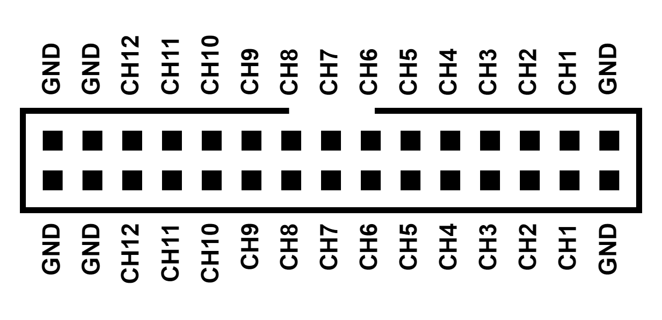
- Grounded connection Capacitances are said to be "grounded" if they are connected according to the schematics shown below. Set the connection parameter in the configuration file as "grounded".
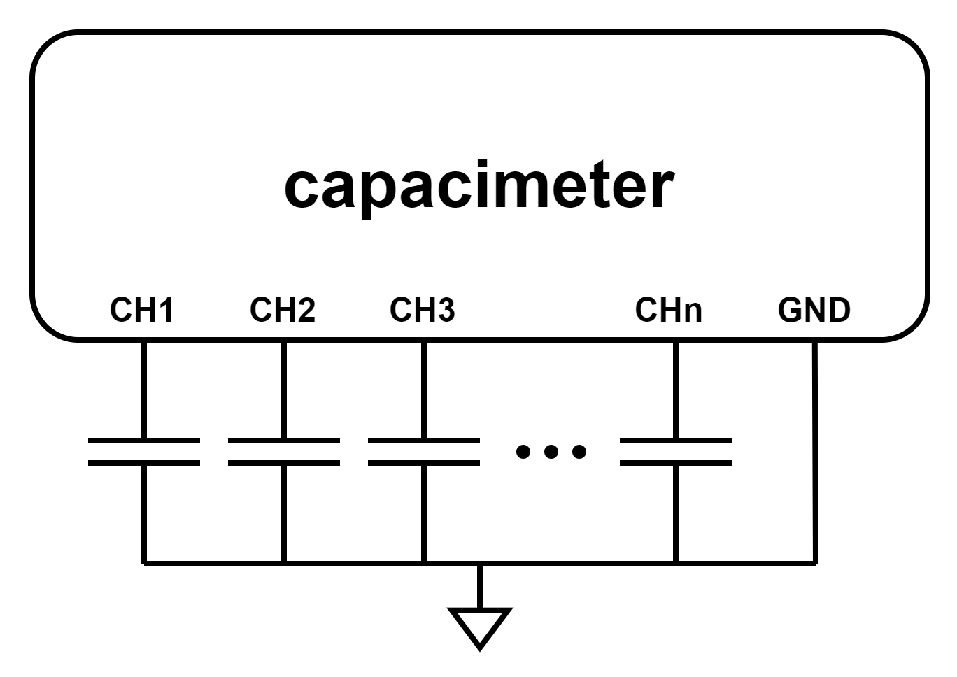
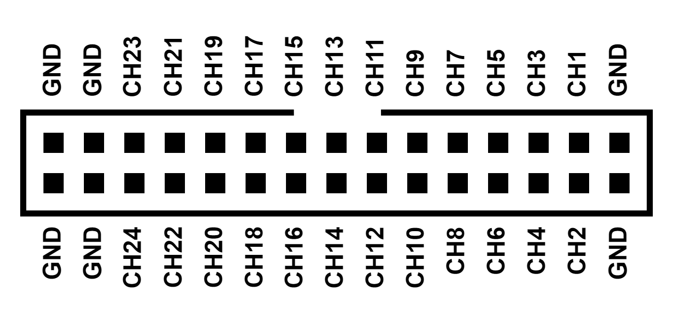
In this setup, the pinout of the capacimeter's connector is as depicted in the figure below (front view). When using "grounded" connection configuration, 24 channels are available as only one pin of the capacitance needs to be connected to the capacimeter. Any of the connector's ground pins can be used as reference because they are all connected together within the device.
- Floating connection
Capacitances are said to be "floating" when they are not (or must not) be connected to ground. Set the connection parameter in the configuration file as "floating". In this configuration, two pins of the capacimeter are needed to measure one capacitance which must be connected according to the schematics shown below.
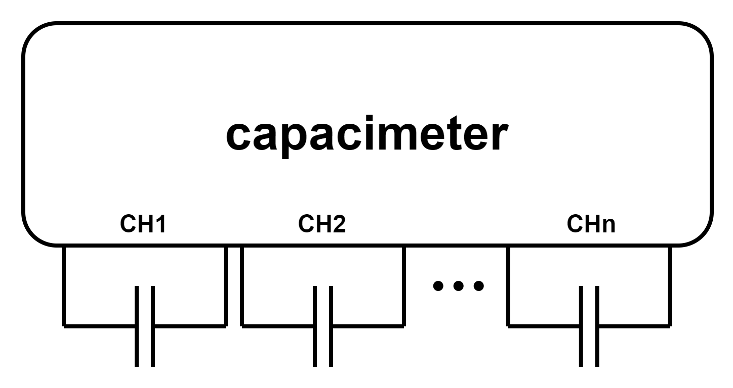
When the capacimeter is set to "floating" connection mode, the pinout of the connector adheres to the diagram depicted below. It offers up to 12 channels, and there is no need to connect the ground pins.
Capacimeter configuration (sensor setup)
This device is compatible with Contextual Instruments' mobile app. Please visit the Apple Store or Google Play to download it. In LIVE mode, you can specify the parameters of your acquisition in a sensor setup. The capacimeter sensor setup is composed of the following elements.
-
Connection: Specify "grounded" or "floating" to indicate whether the capacitance being measured is connected to ground or left unconnected. Refer to the following section, "Get you capacimeter ready : the connection" for further details.
-
Number of channel: The number of channel to acquire. In grounded mode this can be up to 24 while in floating mode, the maximum number of channels is 12.
-
Sampling Interval: The Sampling Interval is adjustable from 50ms to 10000ms.
Capacimeter states
| State | LED Status | Definition |
|---|---|---|
| Charging | solid green | A suitable power source is connected and the device is fully charged |
| Charging | solid yellow | A suitable power source is connected and the device is charging |
| Sleep mode | off | The device is in sleep mode (or the battery is depleted). A long press on the button, regardless of the current state, puts the product into sleep mode |
| IDLE | blinking green | Pressing the button while the device is in sleep mode wakes it up. Then the device is in IDLE mode, ready to measure |
| IDLE | solid red | The device is in IDLE mode and battery is inferior to 20% |
| Preparing | solid blue | The device is connected to the smartphone and ready for the measurement to start. |
| Measurement | blinking blue | The device is measuring. |
| Error | blinking red | The device encountered an issue while preparing for measurement. After 5 seconds, it will automatically return to Sleep mode. |
| Low battery | blinking red | The device won’t start because the battery is very low. |
Resetting the device
Unplug the Capacimeter from any external power source by simply disconnecting the USB cable if it is connected. Then, use a small pin, such as a paperclip, to press the reset button through the tiny hole in the case.
CSV file
The CSV file of Capacimeter measurements is structured in two parts: measurement metadata, and the raw data.
Metadata
| Title | Definition |
|---|---|
| Sensor setup | Sensor setup name. |
| Sensor setup id | Sensor setup ID. |
| Sensor SN | Sensor Serial Number. This number is printed on the device. |
| Experimenter | Experimenter name. |
| Firmware version | Capacimeter firmware version. |
| Date | Measurement timestamp. |
| Timezone | Timestamp timezone. The time zone associated with the recorded timestamp. |
| User note | User comments provided in the dedicated field. |
| Result data type(s) | Type of Acquired Data. |
| Device | Device type used. |
| Connection | See Capacimeter configuration part. |
| Number of channels | See Capacimeter configuration part. |
| Sampling interval | See Capacimeter configuration part. |
Raw data
The raw dataset includes 1 + n columns: Time from start (µs), Channel 1 (nF), Channel 1 (nF), ..., Channel n (nF).